這時就必須靠外掛的RTC模組來維持時間的運作。

這款是用CR 2032 水銀電池 (靠~

簡講描述一下,第一次使用(或是移除電池後)時需要設定正確的時間,之後只要在電池
有電的情況下,它自己會滴答滴答的走~下次需要時再讀取它的時間即可。
接線方法如下:
DS1302 Arduino
VCC 5V
GND GND
CLK D6
DAT D7
RST D8
接下來是官網找到的程式碼
http://playground.arduino.cc/Main/DS1302
// Range
// -----
//      seconds : 00-59
//      minutes : 00-59
//      hour    : 1-12 or 0-23
//      date    : 1-31
//      month   : 1-12
//      day     : 1-7
//      year    : 00-99
//
//

// Set your own pins with these defines !
#define DS1302_SCLK_PIN   6    // Arduino pin for the Serial Clock
#define DS1302_IO_PIN     7    // Arduino pin for the Data I/O
#define DS1302_CE_PIN     8    // Arduino pin for the Chip Enable


// Macros to convert the bcd values of the registers to normal
// integer variables.
// The code uses separate variables for the high byte and the low byte
// of the bcd, so these macros handle both bytes separately.
#define bcd2bin(h,l)    (((h)*10) + (l))
#define bin2bcd_h(x)   ((x)/10)
#define bin2bcd_l(x)    ((x)%10)


// Register names.
// Since the highest bit is always '1',
// the registers start at 0x80
// If the register is read, the lowest bit should be '1'.
#define DS1302_SECONDS           0x80
#define DS1302_MINUTES           0x82
#define DS1302_HOURS             0x84
#define DS1302_DATE              0x86
#define DS1302_MONTH             0x88
#define DS1302_DAY               0x8A
#define DS1302_YEAR              0x8C
#define DS1302_ENABLE            0x8E
#define DS1302_TRICKLE           0x90
#define DS1302_CLOCK_BURST       0xBE
#define DS1302_CLOCK_BURST_WRITE 0xBE
#define DS1302_CLOCK_BURST_READ  0xBF
#define DS1302_RAMSTART          0xC0
#define DS1302_RAMEND            0xFC
#define DS1302_RAM_BURST         0xFE
#define DS1302_RAM_BURST_WRITE   0xFE
#define DS1302_RAM_BURST_READ    0xFF


// Defines for the bits, to be able to change
// between bit number and binary definition.
// By using the bit number, using the DS1302
// is like programming an AVR microcontroller.
// But instead of using "(1<<X)", or "_BV(X)",
// the Arduino "bit(X)" is used.
#define DS1302_D0 0
#define DS1302_D1 1
#define DS1302_D2 2
#define DS1302_D3 3
#define DS1302_D4 4
#define DS1302_D5 5
#define DS1302_D6 6
#define DS1302_D7 7


// Bit for reading (bit in address)
#define DS1302_READBIT DS1302_D0 // READBIT=1: read instruction

// Bit for clock (0) or ram (1) area,
// called R/C-bit (bit in address)
#define DS1302_RC DS1302_D6

// Seconds Register
#define DS1302_CH DS1302_D7   // 1 = Clock Halt, 0 = start

// Hour Register
#define DS1302_AM_PM DS1302_D5 // 0 = AM, 1 = PM
#define DS1302_12_24 DS1302_D7 // 0 = 24 hour, 1 = 12 hour

// Enable Register
#define DS1302_WP DS1302_D7   // 1 = Write Protect, 0 = enabled

// Trickle Register
#define DS1302_ROUT0 DS1302_D0
#define DS1302_ROUT1 DS1302_D1
#define DS1302_DS0   DS1302_D2
#define DS1302_DS1   DS1302_D2
#define DS1302_TCS0  DS1302_D4
#define DS1302_TCS1  DS1302_D5
#define DS1302_TCS2  DS1302_D6
#define DS1302_TCS3  DS1302_D7


// Structure for the first 8 registers.
// These 8 bytes can be read at once with
// the 'clock burst' command.
// Note that this structure contains an anonymous union.
// It might cause a problem on other compilers.
typedef struct ds1302_struct
{
  uint8_t Seconds:4;      // low decimal digit 0-9
  uint8_t Seconds10:3;    // high decimal digit 0-5
  uint8_t CH:1;           // CH = Clock Halt
  uint8_t Minutes:4;
  uint8_t Minutes10:3;
  uint8_t reserved1:1;
  union
  {
    struct
    {
      uint8_t Hour:4;
      uint8_t Hour10:2;
      uint8_t reserved2:1;
      uint8_t hour_12_24:1; // 0 for 24 hour format
    } h24;
    struct
    {
      uint8_t Hour:4;
      uint8_t Hour10:1;
      uint8_t AM_PM:1;      // 0 for AM, 1 for PM
      uint8_t reserved2:1;
      uint8_t hour_12_24:1; // 1 for 12 hour format
    } h12;
  };
  uint8_t Date:4;           // Day of month, 1 = first day
  uint8_t Date10:2;
  uint8_t reserved3:2;
  uint8_t Month:4;          // Month, 1 = January
  uint8_t Month10:1;
  uint8_t reserved4:3;
  uint8_t Day:3;            // Day of week, 1 = first day (any day)
  uint8_t reserved5:5;
  uint8_t Year:4;           // Year, 0 = year 2000
  uint8_t Year10:4;
  uint8_t reserved6:7;
  uint8_t WP:1;             // WP = Write Protect
};


void setup()
{
  ds1302_struct rtc;


  Serial.begin(9600);
  Serial.println(F("DS1302 Real Time Clock"));

  // Start by clearing the Write Protect bit
  // Otherwise the clock data cannot be written
  // The whole register is written,
  // but the WP-bit is the only bit in that register.
  DS1302_write (DS1302_ENABLE, 0);

  // Disable Trickle Charger.
  DS1302_write (DS1302_TRICKLE, 0x00);

// Remove the next define,
// after the right date and time are set.
#define SET_DATE_TIME_JUST_ONCE
#ifdef SET_DATE_TIME_JUST_ONCE

  // Fill these variables with the date and time.
  int seconds, minutes, hours, dayofweek, dayofmonth, month, year;


  // 初次使用,設定目前時間
  seconds    = 0;
  minutes    = 29;
  hours      = 22;
  dayofweek  = 3;  // Day of week, any day can be first, counts 1...7
  dayofmonth = 29; // Day of month, 1...31
  month      = 6;  // month 1...12
  year       = 2016;

  // Set a time and date
  // This also clears the CH (Clock Halt) bit,
  // to start the clock.

  // Fill the structure with zeros to make
  // any unused bits zero
  memset ((char *) &rtc, 0, sizeof(rtc));

  rtc.Seconds    = bin2bcd_l( seconds);
  rtc.Seconds10  = bin2bcd_h( seconds);
  rtc.CH         = 0;      // 1 for Clock Halt, 0 to run;
  rtc.Minutes    = bin2bcd_l( minutes);
  rtc.Minutes10  = bin2bcd_h( minutes);
  // To use the 12 hour format,
  // use it like these four lines:
  //    rtc.h12.Hour   = bin2bcd_l( hours);
  //    rtc.h12.Hour10 = bin2bcd_h( hours);
  //    rtc.h12.AM_PM  = 0;     // AM = 0
  //    rtc.h12.hour_12_24 = 1; // 1 for 24 hour format
  rtc.h24.Hour   = bin2bcd_l( hours);
  rtc.h24.Hour10 = bin2bcd_h( hours);
  rtc.h24.hour_12_24 = 0; // 0 for 24 hour format
  rtc.Date       = bin2bcd_l( dayofmonth);
  rtc.Date10     = bin2bcd_h( dayofmonth);
  rtc.Month      = bin2bcd_l( month);
  rtc.Month10    = bin2bcd_h( month);
  rtc.Day        = dayofweek;
  rtc.Year       = bin2bcd_l( year - 2000);
  rtc.Year10     = bin2bcd_h( year - 2000);
  rtc.WP = 0;

  // 這個只要寫一次,之後除非是電池沒電或是其他原因覺得時間不準。.
  DS1302_clock_burst_write( (uint8_t *) &rtc);
#endif
}


void loop()
{
  ds1302_struct rtc;
  char buffer[80];     // the code uses 70 characters.

  // Read all clock data at once (burst mode).
  DS1302_clock_burst_read( (uint8_t *) &rtc);

  sprintf( buffer, "Time = %02d:%02d:%02d, ", \
    bcd2bin( rtc.h24.Hour10, rtc.h24.Hour), \
    bcd2bin( rtc.Minutes10, rtc.Minutes), \
    bcd2bin( rtc.Seconds10, rtc.Seconds));
  Serial.print(buffer);

  sprintf(buffer, "Date(day of month) = %d, Month = %d, " \
    "Day(day of week) = %d, Year = %d", \
    bcd2bin( rtc.Date10, rtc.Date), \
    bcd2bin( rtc.Month10, rtc.Month), \
    rtc.Day, \
    2000 + bcd2bin( rtc.Year10, rtc.Year));
  Serial.println( buffer);

  delay( 5000);
}


// --------------------------------------------------------
// DS1302_clock_burst_read
//
// This function reads 8 bytes clock data in burst mode
// from the DS1302.
//
// This function may be called as the first function,
// also the pinMode is set.
//
void DS1302_clock_burst_read( uint8_t *p)
{
  int i;

  _DS1302_start();

  // Instead of the address,
  // the CLOCK_BURST_READ command is issued
  // the I/O-line is released for the data
  _DS1302_togglewrite( DS1302_CLOCK_BURST_READ, true);

  for( i=0; i<8; i++)
  {
    *p++ = _DS1302_toggleread();
  }
  _DS1302_stop();
}


// --------------------------------------------------------
// DS1302_clock_burst_write
//
// This function writes 8 bytes clock data in burst mode
// to the DS1302.
//
// This function may be called as the first function,
// also the pinMode is set.
//
void DS1302_clock_burst_write( uint8_t *p)
{
  int i;

  _DS1302_start();

  // Instead of the address,
  // the CLOCK_BURST_WRITE command is issued.
  // the I/O-line is not released
  _DS1302_togglewrite( DS1302_CLOCK_BURST_WRITE, false);

  for( i=0; i<8; i++)
  {
    // the I/O-line is not released
    _DS1302_togglewrite( *p++, false);
  }
  _DS1302_stop();
}


// --------------------------------------------------------
// DS1302_read
//
// This function reads a byte from the DS1302
// (clock or ram).
//
// The address could be like "0x80" or "0x81",
// the lowest bit is set anyway.
//
// This function may be called as the first function,
// also the pinMode is set.
//
uint8_t DS1302_read(int address)
{
  uint8_t data;

  // set lowest bit (read bit) in address
  bitSet( address, DS1302_READBIT);

  _DS1302_start();
  // the I/O-line is released for the data
  _DS1302_togglewrite( address, true);
  data = _DS1302_toggleread();
  _DS1302_stop();

  return (data);
}


// --------------------------------------------------------
// DS1302_write
//
// This function writes a byte to the DS1302 (clock or ram).
//
// The address could be like "0x80" or "0x81",
// the lowest bit is cleared anyway.
//
// This function may be called as the first function,
// also the pinMode is set.
//
void DS1302_write( int address, uint8_t data)
{
  // clear lowest bit (read bit) in address
  bitClear( address, DS1302_READBIT);

  _DS1302_start();
  // don't release the I/O-line
  _DS1302_togglewrite( address, false);
  // don't release the I/O-line
  _DS1302_togglewrite( data, false);
  _DS1302_stop();
}


// --------------------------------------------------------
// _DS1302_start
//
// A helper function to setup the start condition.
//
// An 'init' function is not used.
// But now the pinMode is set every time.
// That's not a big deal, and it's valid.
// At startup, the pins of the Arduino are high impedance.
// Since the DS1302 has pull-down resistors,
// the signals are low (inactive) until the DS1302 is used.
void _DS1302_start( void)
{
  digitalWrite( DS1302_CE_PIN, LOW); // default, not enabled
  pinMode( DS1302_CE_PIN, OUTPUT);

  digitalWrite( DS1302_SCLK_PIN, LOW); // default, clock low
  pinMode( DS1302_SCLK_PIN, OUTPUT);

  pinMode( DS1302_IO_PIN, OUTPUT);

  digitalWrite( DS1302_CE_PIN, HIGH); // start the session
  delayMicroseconds( 4);           // tCC = 4us
}


// --------------------------------------------------------
// _DS1302_stop
//
// A helper function to finish the communication.
//
void _DS1302_stop(void)
{
  // Set CE low
  digitalWrite( DS1302_CE_PIN, LOW);

  delayMicroseconds( 4);           // tCWH = 4us
}


// --------------------------------------------------------
// _DS1302_toggleread
//
// A helper function for reading a byte with bit toggle
//
// This function assumes that the SCLK is still high.
//
uint8_t _DS1302_toggleread( void)
{
  uint8_t i, data;

  data = 0;
  for( i = 0; i <= 7; i++)
  {
    // Issue a clock pulse for the next databit.
    // If the 'togglewrite' function was used before
    // this function, the SCLK is already high.
    digitalWrite( DS1302_SCLK_PIN, HIGH);
    delayMicroseconds( 1);

    // Clock down, data is ready after some time.
    digitalWrite( DS1302_SCLK_PIN, LOW);
    delayMicroseconds( 1);        // tCL=1000ns, tCDD=800ns

    // read bit, and set it in place in 'data' variable
    bitWrite( data, i, digitalRead( DS1302_IO_PIN));
  }
  return( data);
}


// --------------------------------------------------------
// _DS1302_togglewrite
//
// A helper function for writing a byte with bit toggle
//
// The 'release' parameter is for a read after this write.
// It will release the I/O-line and will keep the SCLK high.
//
void _DS1302_togglewrite( uint8_t data, uint8_t release)
{
  int i;

  for( i = 0; i <= 7; i++)
  {
    // set a bit of the data on the I/O-line
    digitalWrite( DS1302_IO_PIN, bitRead(data, i));
    delayMicroseconds( 1);     // tDC = 200ns

    // clock up, data is read by DS1302
    digitalWrite( DS1302_SCLK_PIN, HIGH);
    delayMicroseconds( 1);     // tCH = 1000ns, tCDH = 800ns

    if( release && i == 7)
    {
      // If this write is followed by a read,
      // the I/O-line should be released after
      // the last bit, before the clock line is made low.
      // This is according the datasheet.
      // I have seen other programs that don't release
      // the I/O-line at this moment,
      // and that could cause a shortcut spike
      // on the I/O-line.
      pinMode( DS1302_IO_PIN, INPUT);

      // For Arduino 1.0.3, removing the pull-up is no longer needed.
      // Setting the pin as 'INPUT' will already remove the pull-up.
      // digitalWrite (DS1302_IO, LOW); // remove any pull-up
    }
    else
    {
      digitalWrite( DS1302_SCLK_PIN, LOW);
      delayMicroseconds( 1);       // tCL=1000ns, tCDD=800ns
    }
  }
}
主要的函式只有2個
DS1302_write 以及 S1302_read
分別代表寫入時間到RTC以及由RTC讀取時間。
寫入時間只要一次即可,因為這是範例,所以會寫在Setting中。
比較理想的做法是,每隔一段時間去跟網路校時,然候把時時間寫入RTC中,
平常就靠RTC來取得時間即可。
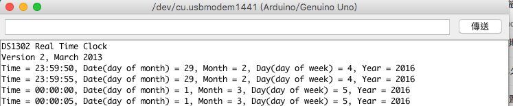
以下是執行結果,我放著測了半個多小時,跨過24點時,Date(day of month)自動+1

接下來我們做個測試,調成6月30日晚上23:59,看看隔一天是什麼

看起來會自動跳成七月31日,沒有問題,接下來是7月31日看看, 會自動跳8月1日

接下來是2016年2月29日,順利跳成3月1日
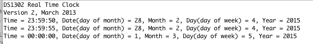
我們試試沒有潤年的2015年2月29日設定看看,oh~no ,Bug出現了,2月30日。

再試試2015年的2月28日隔天會跳什麼,跳3月1日很正常。
如果是2016年的2月28日,會跳2月29日,沒有問題。

接下來是寫入不合理的時間,2016年13月31日,隔天變成4月1日

跨年也沒有問題

超過24小時看看,26點變成2

好吧,來PLAY惡搞分鐘,看起來66分下一分鐘會變成67分,這也是個Bug。

看起來只要設定正確的時間,都不會有問題,但是如果是設不合法的時間,就會出現問題。
參考連結:
http://siang-tong-studio.blogspot.tw/2015/05/24.html
http://scicorek.blogspot.tw/2015/01/ds1302-rtc.html
http://playground.arduino.cc/Main/DS1302


