2017年3月27日 星期一

「智語」上善若水

上善若水,水善利萬物而不爭,處為人之所惡,故幾於道。
居善地,心善淵,與善仁,言善信,正善治,事善能,動善時。夫唯不爭,故無尤。


  有道德的人就像水,水能夠跟萬物融合卻不會跟萬物相爭,還能處在大家都討厭的低下

地方,因為這些特性所以可以說水跟道很接近了。

        有道德的人像水處在低下的地方一樣的謙虛,心就像水一樣的淵博沈靜,

付出就像水滋養萬物一樣的不求回報,言行就像水照萬物的清晰一樣的有誠信,

為政就像水能除垢一樣的有政績,做事就像水能方能圓一樣的有最好的功用,

行動就像水能隨順外物變化一樣的順應時勢。有道德的人就像水的不爭,

因為不計較所以就沒有怨尤。


資料來源:

2017年3月26日 星期日

[Arduino]RS485 初嘗

買了一塊WaveShare 的UART轉RS485(5V)板子來玩玩看。

先簡介一下RS485:

EIA-485(過去叫做RS-485或者RS485])是隸屬於OSI模型實體層的電氣特性規定為2線,半雙工,多點通訊的標準。它的電氣特性和RS-232不大一樣。用纜線兩端的電壓差值來表示傳遞訊號,1極的電壓標識為邏輯1,另一段標識為邏輯0。兩端的電壓差最小為0.2V以上時有效,任何不大於12V或者不小於-7V的差值對接受端都被認為是正確的。

EIA-485僅僅規定了接受端和傳送端的電氣特性。它沒有規定或推薦任何資料協定。EIA-485可以應用於配置便宜的廣域網路和採用單機傳送,多機接受通訊連結。它提供高速的資料通訊速率(10m時35Mbit/s;1200m時100kbit/s)。EIA-485和EIA-422一樣使用雙絞線進行高電壓差分平衡傳輸,它可以進行大面積長距離傳輸(超過4000英尺,1200公尺)。
EIA-485經常和常用裝置UART一起使用來實現在飛機上的低速率資料傳輸,舉個例子,一些乘客控制單元採用這種裝置,從而只需要很少的線纜就可以實現幾端子共享線纜,從而減輕整個裝置的重量。

                                                          所以RS485上會常見到一些協定,例如Modbus,BacNet and Profibus  。

當然RS485 也可以利用2組A/B來達成全雙工(一對專送,一對專收)

以上資料來源:

EIA-485 WIKI


簡單來說,RS485並沒有規定使用任何界面,只要電氣特性相符即可。

最左邊是接UART , 你可以看到它提供3種介面的RS485 A/B ,除了杜邦線之外就是2P端子 ,以及一個


腳立說明如下,資料來源:


主要特點為RSE這一支腳,它控制了資料流的方向,當RSE為HIGH時,代表要送資料,

RSE為LOW時表示要接收資料,所以一開始Master會預設為發送,remote會預設為接收。


由於RS485是半雙工的通訊方式,所以每一個裝都只能是傳送或是接收其中一種狀態。

參考了以下網址的範例。

https://arduino-info.wikispaces.com/SoftwareSerialRS485Example

這個範例master每次只能傳送一個byte,然候就會切換到接收模式直到Serial有再次輸入,就會切回去發送模式(此時remote傳再多它也收不到了),而remote在接收到資料後會切換成傳送模式把資料發送回去,10ms後就會再回到接收模式。


接腳如下:

arduino              RS485
10                        RX
11                        TX
3                         RSE
5V                       VCC
GND                    GDN 

二塊板子之間的A接A,B接B。


之後燒錄程式,一邊為Master,一邊為remote


Master端程式如下:

/* YourDuino SoftwareSerialExample1
   - Connect to another Arduino running "YD_SoftwareSerialExampleRS485_1Remote"
   - Connect this unit Pins 10, 11, Gnd
   - Pin 3 used for RS485 direction control
   - To other unit Pins 11,10, Gnd  (Cross over)
   - Open Serial Monitor, type in top window. 
   - Should see same characters echoed back from remote Arduino

   Questions: terry@yourduino.com 
*/

/*-----( Import needed libraries )-----*/
#include <SoftwareSerial.h>
/*-----( Declare Constants and Pin Numbers )-----*/
#define SSerialRX        10  //Serial Receive pin
#define SSerialTX        11  //Serial Transmit pin

#define SSerialTxControl 3   //RS485 Direction control

#define RS485Transmit    HIGH
#define RS485Receive     LOW

#define Pin13LED         13

/*-----( Declare objects )-----*/
SoftwareSerial RS485Serial(SSerialRX, SSerialTX); // RX, TX

/*-----( Declare Variables )-----*/
int byteReceived;
int byteSend;

void setup()   /****** SETUP: RUNS ONCE ******/
{
  // Start the built-in serial port, probably to Serial Monitor
  Serial.begin(9600);
  Serial.println("YourDuino.com SoftwareSerial remote loop example");
  Serial.println("Use Serial Monitor, type in upper window, ENTER");
  
  pinMode(Pin13LED, OUTPUT);   
  pinMode(SSerialTxControl, OUTPUT);    
  
  digitalWrite(SSerialTxControl, RS485Receive);  // Init Transceiver   
  
  // Start the software serial port, to another device
  RS485Serial.begin(4800);   // set the data rate 

}//--(end setup )---


void loop()   /****** LOOP: RUNS CONSTANTLY ******/
{
  digitalWrite(Pin13LED, HIGH);  // Show activity
  if (Serial.available())
  {
    byteSend = Serial.read();
    digitalWrite(SSerialTxControl, RS485Transmit);  // Enable RS485 Transmit   
    RS485Serial.write(byteSend);          // Send byte to Remote Arduino
    digitalWrite(Pin13LED, LOW);  // Show activity    
    delay(10);
    digitalWrite(SSerialTxControl, RS485Receive);  // Disable RS485 Transmit       
   
  }
    
  if (RS485Serial.available())  //Look for data from other Arduino
   {
    digitalWrite(Pin13LED, HIGH);  // Show activity
    byteReceived = RS485Serial.read();    // Read received byte
    if (byteReceived!=0 && byteReceived!=10 && byteReceived!=13)
     {
        Serial.print("receive:");        // Show on Serial Monitor
        Serial.write(byteReceived);
        Serial.println();
     }
     
    delay(10);
    digitalWrite(Pin13LED, LOW);  // Show activity   
   }  

}//--(end main loop )---

/*-----( Declare User-written Functions )-----*/

//NONE
//*********( THE END )***********

remote端如下

/* YourDuino SoftwareSerialExample1Remote
   - Used with YD_SoftwareSerialExampleRS485_1 on another Arduino
   - Remote: Receive data, loop it back...
   - Connect this unit Pins 10, 11, Gnd
   - To other unit Pins 11,10, Gnd  (Cross over)
   - Pin 3 used for RS485 direction control   
   - Pin 13 LED blinks when data is received  
   
   Questions: terry@yourduino.com 
*/

/*-----( Import needed libraries )-----*/
#include <SoftwareSerial.h>
/*-----( Declare Constants and Pin Numbers )-----*/
#define SSerialRX        10  //Serial Receive pin
#define SSerialTX        11  //Serial Transmit pin

#define SSerialTxControl 3   //RS485 Direction control
#define RS485Transmit    HIGH
#define RS485Receive     LOW

#define Pin13LED         13

/*-----( Declare objects )-----*/
SoftwareSerial RS485Serial(SSerialRX, SSerialTX); // RX, TX

/*-----( Declare Variables )-----*/
int byteReceived;
int byteSend;

void setup()   /****** SETUP: RUNS ONCE ******/
{
  // Start the built-in serial port, probably to Serial Monitor
  Serial.begin(9600);
  Serial.println("SerialRemote");  // Can be ignored
  
  pinMode(Pin13LED, OUTPUT);   
  pinMode(SSerialTxControl, OUTPUT);  
  
  digitalWrite(SSerialTxControl, RS485Receive);  // Init Transceiver
  
  // Start the software serial port, to another device
  RS485Serial.begin(4800);   // set the data rate 
}//--(end setup )---


void loop()   /****** LOOP: RUNS CONSTANTLY ******/
{
  //Copy input data to output  
  if (RS485Serial.available()) 
  {
    byteSend = RS485Serial.read();   // Read the byte 
    digitalWrite(Pin13LED, HIGH);  // Show activity
    delay(10);              
    digitalWrite(Pin13LED, LOW);   
    Serial.write(byteSend);
    digitalWrite(SSerialTxControl, RS485Transmit);  // Enable RS485 Transmit    
    if (byteSend!=0 && byteSend!=10 && byteSend!=13)
        RS485Serial.write(byteSend); // Send the byte back
    delay(10);   
    digitalWrite(SSerialTxControl, RS485Receive);  // Disable RS485 Transmit      
//    delay(100);
  }// End If RS485SerialAvailable
  
}//--(end main loop )---

/*-----( Declare User-written Functions )-----*/
//NONE

//*********( THE END )***********

程式碼來源:(我有稍微做一點修改)
https://arduino-info.wikispaces.com/SoftwareSerialRS485Example

master執行畫面(記得選擇為沒有結尾)


remote執行畫面(使用CoolTerm)
記得先修改一下傳送的結尾模式


由master傳送一個字元a,會收到一個相同回應


remote端也會將收到的字元顯示並回傳給Master


如果一次輸入一堆字傳送,可能就會出現問題,例如我輸入1234567890abcdefg


remote端收到的也是不正確的字元


所以使用rs485做傳輸時,一定要注意收和送的時間點,建議使用現有的協定,例如ModBus,因為在收和送之間需要切換,這個如果沒有搭配好,會出現異常的資料。

2017年3月17日 星期五

[Arduino] EEPROM


EEPROM,或寫作E2PROM,全稱電子抹除式可複寫唯讀記憶體 (英語:Electrically-
Erasable Programmable Read-Only Memory),是一種可以通過電子方式多次複寫的半導
體存儲裝置。相比EPROM,EEPROM不需要用紫外線照射,也不需取下,就可以用特定的
電壓,來抹除晶片上的資訊,以便寫入新的資料。

EEPROM有四種工作模式:讀取模式、寫入模式、擦拭模式、校驗模式。
讀取時,晶片只需要Vcc低電壓(一般+5V)供電。編程寫入時,
晶片通過Vpp(一般+25V, 較新者可能使用 12V 或 5V)獲得編程電壓,
並通過PGM編程脈衝(一般50ms)寫入資料。擦拭時,只需使用Vpp高電壓,
不需要紫外線,便可以擦拭指定位址的內容。為保證寫入正確,在每寫入一塊資料後,
都需要進行類似於讀取的校驗步驟,若錯誤就重新寫入。
現今的 EEPROM 通常已不再需要使用額外的 Vpp 電壓,且寫入時間也已有縮短。


以上資料來源:

電子抹除式可複寫唯讀記憶體https://zh.wikipedia.org/wiki/%E9%9B%BB%E5%AD%90%E6%8A%B9%E9%99%A4%E5%BC%8F%E5%8F%AF%E8%A4%87%E5%AF%AB%E5%94%AF%E8%AE%80%E8%A8%98%E6%86%B6%E9%AB%94


在Arduino的微控器晶片內,其實有0.5KB到4KB不等的EEPROM記憶體(視MCU不同而有差異),可以用來儲存一些斷電後仍要留存的資料。

EEPROM 有寫入次數的限制,ATmega 系列微控制器的 EEPROM 其每一個位置大約只能寫入 10 萬次,在使用的時候,最好盡量公平對待 EEPROM 的每一塊空間,不要對特定一個位置一直寫入,如果頻繁地使用固定的一塊位置,那麼該塊空間壽命會急速縮短。

以下是不同Arduino Chip EEPROM大小

Chip Sizp
ATmega328 1024 bytes
ATmega168 512 bytes
ATmega8 1024 bytes
ATmega1280 4KB (4096 bytes)
ATmega2560 4KB (4096 bytes)

參考資料來源:
http://coopermaa2nd.blogspot.tw/2010/12/arduino-eeprom.html
以下是EEPROM API

  • EEPROM Clear: Clear the bytes in the EEPROM. 
  • 清除所有EEPROM資料(所以位址都將使用了一次)
  • EEPROM Read: Read the EEPROM and send its values to the computer.
  • 讀取指定的位址(一個byte)
  • EEPROM Write: Stores values from an analog input to the EEPROM.
  • 把資料寫入指定的位址(一個byte)
  • EEPROM Crc: Calculates the CRC of EEPROM contents as if it was an array.
  • 計算整個EEPROM的CRC ,確認資料是否正確。
  • EEPROM Get: Get values from EEPROM and prints as float on serial.
  • 一次取得n個byte的資料,例如float是4個byte。
  • EEPROM Iteration: Understand how to go through the EEPROM memory locations.
  • 說明如何透過EEPROM儲存資料。
  • EEPROM Put: Put values in EEPROM using variable semantics.
  • 一次放入n個byte的資料,例如我可以直接把float寫入連入4個byte。
  • EEPROM Update: Stores values read from A0 into EEPROM, writing the value only if different, to increase EEPROM life.
  • update和write不同在於,如果此位址中的資料和欲寫入的相同,則不寫,節省一次EEPROM位址的存取。

參考資料來源:

http://makerpro.cc/2015/05/arduino%CA%BBs-new-eeprom-libraries/
要使用EEPROM,必須引入EEPROM.h

首先我們先來取得一下EEPROM大小

#include <EEPROM.h>

void setup() {
  // put your setup code here, to run once:
  Serial.begin(9600);

 Serial.print("EEPROM length: ");
 Serial.println(EEPROM.length());
 
   
}

void loop() {
  // put your main code here, to run repeatedly:

}

執行結果


寫入位置0,再讀取位址0
#include <EEPROM.h>

void setup() {
  // put your setup code here, to run once:
  Serial.begin(9600);


  EEPROM.write(0,10);

  byte b=EEPROM.read(0);

  Serial.println(b);
}

void loop() {
  // put your main code here, to run repeatedly:

}

執行結果


接下來我們把寫入那行註解起來,上傳程式碼,然候我們斷電再接上看看。


#include <EEPROM.h>

void setup() {
  // put your setup code here, to run once:
  Serial.begin(9600);


  //EEPROM.write(0,10);

  byte b=EEPROM.read(0);

  Serial.println(b);
}

void loop() {
  // put your main code here, to run repeatedly:

}

執行結果。


接下來我們來試試put和get


#include <EEPROM.h>

void setup() {
  // put your setup code here, to run once:
  Serial.begin(9600);


  //EEPROM.write(0,10);

  byte b=EEPROM.read(0);

  Serial.println(b);


  float pi=3.14159;
  EEPROM.put(2,pi);

  float readfloat=0;
  
  EEPROM.get(2,readfloat);
  Serial.println(readfloat);
  
}

void loop() {
  // put your main code here, to run repeatedly:

}

執行結果,看起來float寫入EEPROM有精度問題,只能存4個byte,3.14159只能寫入3.14


2017年3月16日 星期四

[Java] Transpose Array

Transpose Array :

將Array的 由橫向變成縱向(相反亦同)。

Ex:

1 2 3 4
5 6 7 8 
9 10 11 12

 
變成
1 5 9 
2 6 10
3 7 11 
4 8 12

範例程式碼如下:


public class Testtranspose
{  
  public static void main(String[] args)
  {
    
    final int[][] original = new int[][] { { 1, 2, 3, 4 }, { 5, 6, 7, 8 }, { 9, 10, 11, 12 } };
        for (int i = 0; i < original.length; i++) {
            for (int j = 0; j < original[i].length; j++) {
                System.out.print(original[i][j] + " ");
            }
            System.out.print("\n");
        }
        int[][] tranposeArray=transpose(original) ;
     for (int i = 0; i < original[0].length; i++) {
                for (int j = 0; j < original.length; j++) {
                    System.out.print(original[j][i] + " ");                   
                }
                System.out.print("\n");
            }
   }
  
  public static int[][] transpose(int[][] original) {

        int[][] transposeArray=new int[original[0].length][original.length];
        System.out.print("\n\n matrix transpose:\n");
        // transpose
        if (original.length > 0) {
            for (int i = 0; i < original[0].length; i++) {
                for (int j = 0; j < original.length; j++) {                  
                   transposeArray[i][j]=original[j][i];
                }
            }
        }
     return transposeArray;
    }
}


參考資料來源:
http://stackoverflow.com/questions/8422374/java-multi-dimensional-array-transposing

「電路」XLR 3 pin 與 5 Pin 轉換

雖然DMX-512標準要求使用5 pin XLR連接器,但一些DMX控制設備使用3 pin XLR連接器

(通常因為它們的成本較低)。 所以需要在5 pin和3 pin 電纜和固定裝置之間進行轉換。

製做5 pin 到3 pin XLR轉接器的標準做法是

將pin 1連接到pin 1,pin 2到pin 2和pin 3到pin 3.

將5 pin XLR連接器上的pin 4和pin 5保持未連接:

5-Pin XLR3-Pin XLRSignal
Pin 1Pin 1Signal Ground
Pin 2Pin 2DMX Data -
Pin 3Pin 3DMX Data +
Pin 4n/cAuxiliary Data -
Pin 5n/cAuxiliary Data


在一些較舊的Martin Professional夾具上使用3針XLR插孔,pin 2和pin 3相反。

在這種情況下,轉接器需要以不同的方式連接,pin 1到pin 1,pin 2到pin 3和pin 3到pin2。


資料來源:


http://interactive-online.com/support/forum/5-pin-to-3-pin-xlr-adapter-wiring


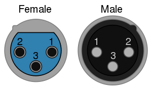
注意一件事,XLR 公頭和母頭pin1 ~pin 5 順序剛好相反


圖片資料來源:
https://www.medialon.com/support/faq/how-to-convey-dmx512-over-rj45/


https://mediarealm.com.au/articles/2013/04/xlr-wiring-standard-3-pin-5-pin/


所以正確的接法應該如下圖:

A 3-pin to 5-pin adapter uses a Male公) 3-pin and Female(母) 5-pin XLR connectors.


A 5-pin to 3-pin adapter uses a Male(公) 5-pin and Female(母) 3-pin XLR connectors.


有時候會看到phone jack 3.5mm to XLR


或是用4節的phone jack ( 其中第3節是沒有用到的)


2017年3月15日 星期三

[名詞定義]XLR端子

XLR端子是影音器材中常見的端子,經常用於連接專業影音器材和麥克風

XLR端子常俗稱為Cannon插頭或Cannon端子,XLR端子的針頭基本上三個外,

還可以有更大針頭數。

XLR端子和以前更細小的DIN端子有點相似,但實際上是不相容的。


XLR3纜線插頭,圖片左為母頭右為公頭。

EIA RS-297-A標準描述了使用XLR3端子作平衡音訊的用法:
XLR pinouts.svg
針頭功能
1底架接地(纜線護罩)
2正極終端(熱)
3迴路終端(冷)

以上資料來源:

XLR端子 WIKI

XLR - Cannon X Series Latch Rubber 

適合用於MIX混音器、業務型攝影機、高階錄音機、舞臺音響、新聞發佈會、KTV、

專業擴聲,家庭影院等環境(XLR平衡接頭,將單一聲音分為信號地,信號正/信號負,

高阻介面正負經過處理合併時將可以將干擾信號抵抗力好)


 —俗稱卡儂接頭(Cannon),與RCA(蓮花頭的介面)類比音頻線纜直接傳輸聲音

的方式完全不同,平衡類比音頻(Balanced Analog Audio)介面使用兩個通道分別

傳送信號相同而相位相反的信號。接收端設備將這兩組信號相減,干擾信號就被抵消掉,

從而獲得高品質的類比信號。

以上資料來源:


2017年3月13日 星期一

[ESP8266] Node MCU + DHT22 (OS X)

最近有個需求如下:

1.需要在工作站偵測溫、溼度。

2.需要用MQTT協定回傳資料。

3.無線傳輸。

4.可以用Arduino IDE來寫程式

因而選用Node MCU 搭配DHT 22 。

以下是Node MCU的連結
http://www.nodemcu.com/index_cn.html

Node MCU 可以用Lua語言進行開發,亦可用Arduino IDE進行開發,本篇使用後者。

本次購買的是 LoLin V3 NodeMcu Lua WIFI Development Board


接線圖如下(我買的模組己經裝4.7K做在電路板上了,這只是示意圖)


DHT22 可以運作在3.3 及5V,所以不必擔心電壓問題。

這裡紀錄一個遇到的問題,在程式碼,我指定DHT22 的腳位為2 , 但指的不是D2, 而是GPIO2(D4), 參考下圖(圖片取自網路,如有侵權請來信告知)。


接下來在Arduino IDE中安裝相關的Lib

Adafruit_Sensor
從以下URL下載ZIP檔
https://github.com/adafruit/Adafruit_Sensor


DHT-sensor-lib

https://github.com/adafruit/DHT-sensor-library

下載此ZIP檔


加入.ZIP程式庫。


找到剛才下載的ZIP檔


接下來下載pubsubclient
https://github.com/knolleary/pubsubclient


接下來安裝板子, 打開Arduino的偏好設定,在額外的板子管理員網址加入一行

http://arduino.esp8266.com/stable/package_esp8266com_index.json

按下"好"


接著到板子管理員


安裝一下ESP8266


接下來將板子選擇為Node MCU 1.0 (ESP-12E Module)


接下來要安裝一下USB to UART 驅動,它用的不是和Arduino的一樣,需要額外裝,

否則在序列埠中什麼都看不到。

到這個網址,下載驅動程式,安裝完成後一定要"重開機"

http://www.wch.cn/download/CH341SER_ZIP.html

重開機後開啟Arduino ,輸入以下程式碼。每六秒左右,就會送一次溫溼度到MQTT Server

程式碼如下:
#include "DHT.h"
#include <ESP8266WiFi.h>
#include <PubSubClient.h>

#define DHTPIN 2     // what digital pin we're connected to

#define DHTTYPE DHT22   // DHT 22  (AM2302), AM2321

// NOTE: If using a board with 3.3V logic like an Arduino Due connect pin 1
// to 3.3V instead of 5V!
// Connect pin 2 of the sensor to whatever your DHTPIN is
// Connect pin 4 (on the right) of the sensor to GROUND
// Initialize DHT sensor.
// Note that older versions of this library took an optional third parameter to
// tweak the timings for faster processors.  This parameter is no longer needed
// as the current DHT reading algorithm adjusts itself to work on faster procs.
DHT dht(DHTPIN, DHTTYPE);

// Update these with values suitable for your network.
const char* ssid = "your ssid";
const char* password = "your pw";
const char* mqtt_server = "MQTT Server IP";
const char* topic="your Topic";
// WiFi Client 
WiFiClient espClient;
// PubSub Client
PubSubClient client(espClient); long lastMsg = 0; char msg[50]; int value = 0;

void setup() {
  Serial.begin(9600);
  Serial.println("DHTxx test!");
  setup_wifi();
  client.setServer(mqtt_server, 1883);
  client.setCallback(callback);

  dht.begin();
}

void loop() {
  // Wait a few seconds between measurements.
  delay(2000);
 //Check Wi-Fi is Connected 
  if (WiFi.status() != WL_CONNECTED)
  {
    setup_wifi();
  }
  //Check MQTT Connection 
  if (!client.connected()) {
    reconnect();
  }
  client.loop();

  // Reading temperature or humidity takes about 250 milliseconds!
  // Sensor readings may also be up to 2 seconds 'old' (its a very slow sensor)
  float h = dht.readHumidity();
  // Read temperature as Celsius (the default)
  float t = dht.readTemperature();
  // Read temperature as Fahrenheit (isFahrenheit = true)
  float f = dht.readTemperature(true);

  // Check if any reads failed and exit early (to try again).
  if (isnan(h) || isnan(t) || isnan(f)) {
    Serial.println("Failed to read from DHT sensor!");
    return;
  }

  // Compute heat index in Fahrenheit (the default)
  float hif = dht.computeHeatIndex(f, h);
  // Compute heat index in Celsius (isFahreheit = false)
  float hic = dht.computeHeatIndex(t, h, false);

  Serial.print("Humidity: ");
  Serial.print(h);
  Serial.print(" %\t");
  Serial.print("Temperature: ");
  Serial.print(t);
  Serial.print(" *C ");
  Serial.print(f);
  Serial.print(" *F\t");
  Serial.print("Heat index: ");
  Serial.print(hic);
  Serial.print(" *C ");
  Serial.print(hif);
  Serial.println(" *F");

   long now = millis();
  // read DHT22 sensor every 6 seconds
  if (now - lastMsg > 6000) {
     lastMsg = now;
     String msg=String(h)+","+String(t);
     Serial.println(msg);
     char message[msg.length()];
     msg.toCharArray(message,msg.length());
     //publish sensor data to MQTT broker
    client.publish(topic, message); 
  }
}

void setup_wifi() {
   delay(100);
  // We start by connecting to a WiFi network
    Serial.print("Connecting to ");
    Serial.println(ssid);
    WiFi.begin(ssid, password);
    while (WiFi.status() != WL_CONNECTED) 
    {
      delay(500);
      Serial.print(".");
    }
  randomSeed(micros());
  Serial.println("");
  Serial.println("WiFi connected");
  Serial.println("IP address: ");
  Serial.println(WiFi.localIP());
}
// recieve Topic message handler , I don't implements it 
void callback(char* topic, byte* payload, unsigned int length) { } void reconnect() { // Loop until we're reconnected while (!client.connected()) { Serial.print("Attempting MQTT connection..."); // Create a random client ID String clientId = "ESP8266Client-"; clientId += String(random(0xffff), HEX); // Attempt to connect //if you MQTT broker has clientID,username and password //please change following line to if (client.connect(clientId,userName,passWord)) if (client.connect(clientId.c_str())) { Serial.println("connected"); //once connected to MQTT broker, subscribe command if any client.subscribe(topic); } else { Serial.print("failed, rc="); Serial.print(client.state()); Serial.println(" try again in 5 seconds"); // Wait 6 seconds before retrying delay(6000); } } } //end reconnect()


燒錄完成後,建議按一下RST按鈕,讓它重啟。