2018年12月17日 星期一

[Android] 時間會倒流 ...Orz

最近遇到QC單位跑來說在把手機時間往前調幾小時後,APP失效了,調整前是OK的。

發生問題的程式碼大致上如下

long lastTime=0 ;
long now=0;

public void myFun()
{
    now=System.currentTimeMillis();

    if (now-lastTime>500)
   {
       //do something
      lastTime=now;
   }
}

當QC單位的人操作過一次後last=now 之後,System.currentTimeMillis() 會取出相對於1970/1/1 以來的亳秒,但此時將時間往前幾個小時之後,在這幾個小時內now將持續小於lastTime,因此不會有任何反應。

解決方式是使用絕對值來計算二者時間。


long lastTime=0 ;
long now=0;

public void myFun()
{
    now=System.currentTimeMillis();

    if (Math.abs(now-lasttime)>500)
   {
       //do something
      last=now;
   }
}

時間不會倒流....但手機可以。

2018年11月24日 星期六

[OpenWRT] 用C語言寫UART轉RS485

RS-485 (EIA-485 標準) 為 RS-422 的改良版本,從原本的 10 組裝置
提高至 32 組裝置,僅並定義必要的電子特性,並沒有定義傳輸介面,
所以你會看到有人用普通的單芯線直接連接,或是RJ45/DMX之類的接頭
來做485的傳輸,亦可以混用不同介面在同一個RS-485網路中。

RS485與RS232最大的不同在於它是半雙工,也就是同一時間只能傳送或是接收,RS-485網路中只有同時間有1個以上裝置在發送資料就會出現干擾,所以還會透過Modbus之類的協定來搭配實際的應用。

RS-485是依靠A/B二端的電壓差做為判定1或是0 ,只要A/B之間壓差大於0.2V特,
即判定訊號為1,否則為0 ,RS-485可以接受的電壓範圍比較大,在-7~+12V。

一般的MCU若需要加入RS-485傳輸,則可以透過UART轉RS485 Chip,例如MX232/SP3485等等,透過控制DE/RE腳來控制目前為發送或接收狀態。

程式碼,在AR9331中測試過,DE為PIN 7 ,RE為PIN 13


#include <stdio.h>
#include <stdlib.h>
#include <unistd.h>
#include <fcntl.h>
#include <sys/types.h>
#include <sys/stat.h>
#include <sys/mman.h>
#include <string.h>
#include <time.h>
#include <errno.h>
#include <termios.h>

#define GPIO_ADDR 0x18040000 // base address
#define GPIO_BLOCK 48     // memory block size
char *portname = "/dev/ttyATH0";
volatile unsigned long *gpioAddress;


int set_interface_attribs (int fd, int speed, int parity)
{
        struct termios tty;
        memset (&tty, 0, sizeof tty);
        if (tcgetattr (fd, &tty) != 0)
        {
                printf("error %d from tcgetattr", errno);
                return -1;
        }

        cfsetospeed (&tty, speed);
        cfsetispeed (&tty, speed);

        tty.c_cflag = (tty.c_cflag & ~CSIZE) | CS8;     // 8-bit chars
        // disable IGNBRK for mismatched speed tests; otherwise receive break
        // as \000 chars
        tty.c_iflag &= ~IGNBRK;         // disable break processing
        tty.c_lflag = 0;                // no signaling chars, no echo,
                                        // no canonical processing
        tty.c_oflag = 0;                // no remapping, no delays
        tty.c_cc[VMIN]  = 0;            // read doesn't block
        tty.c_cc[VTIME] = 5;            // 0.5 seconds read timeout

        tty.c_iflag &= ~(IXON | IXOFF | IXANY); // shut off xon/xoff ctrl

        tty.c_cflag |= (CLOCAL | CREAD);// ignore modem controls,
                                        // enable reading
        tty.c_cflag &= ~(PARENB | PARODD);      // shut off parity
        tty.c_cflag |= parity;
        tty.c_cflag &= ~CSTOPB;
        tty.c_cflag &= ~CRTSCTS;

        if (tcsetattr (fd, TCSANOW, &tty) != 0)
        {
                printf ("error %d from tcsetattr", errno);
                return -1;
        }
        return 0;
}

void set_blocking (int fd, int should_block)
{
        struct termios tty;
        memset (&tty, 0, sizeof tty);
        if (tcgetattr (fd, &tty) != 0)
        {
                printf ("error %d from tggetattr", errno);
                return;
        }

        tty.c_cc[VMIN]  = should_block ? 1 : 0;
        tty.c_cc[VTIME] = 5;            // 0.5 seconds read timeout

        if (tcsetattr (fd, TCSANOW, &tty) != 0)
                printf ("error %d setting term attributes", errno);
}


int gpioRead(int gpio)
{
    unsigned long value = *(gpioAddress + 1);
    //printf("value =%d\n",value);    
    //printf("(1<<gpio) =%d",(1 << gpio));
    return (value & (1 << gpio));
    
}

// "1" (output) or "0" (input) 
void gpioDirection(int gpio, int direction)
{
    unsigned long value = *(gpioAddress + 0); // obtain current settings
    if (direction == 1)
    {
        value |= (1 << gpio); // set bit to 1
    }
    else
    {
        value &= ~(1 << gpio); // clear bit
    }
    *(gpioAddress + 0) = value;
}

void gpioSet(int gpio, int data)
{
    unsigned long value = *(gpioAddress + 2); // obtain current settings
    if (data == 1)
    {
        value |= (1 << gpio); // set bit to 1
    }
    else
    {
        value &= ~(1 << gpio); // clear bit
    }
    *(gpioAddress + 2) = value;
}

/*void gpioSet(int gpio, int value)
{
    if (value == 0)
    {
        *(gpioAddress + 4) = (1 << gpio);
    }
    else
    {
        *(gpioAddress + 3) = (1 << gpio);
    }
}*/

int gpioSetup()
{
    int  m_mfd;
    if ((m_mfd = open("/dev/mem", O_RDWR)) < 0)
    {
        return -1;
    }    
    gpioAddress = (unsigned long*)mmap(NULL, GPIO_BLOCK, PROT_READ|PROT_WRITE, MAP_SHARED, m_mfd, GPIO_ADDR);
    close(m_mfd);

    if (gpioAddress == MAP_FAILED)
    {
        return -2;
    }
    return 0;
}

int main(int argc, char **argv)
{
   int rs485_de=7;
   int rs485_re=13;

   gpioSetup();
   gpioDirection(rs485_de,1);//set pin output
   gpioDirection(rs485_re,1);//set pin output
  
    int fd = open (portname, O_RDWR | O_NOCTTY | O_SYNC);
    if (fd < 0)
    {
            printf ("error %d opening %s: %s", errno, portname, strerror (errno));
            return -1;
    }

    set_interface_attribs (fd, B115200, 0);  // set speed to 115,200 bps, 8n1 (no parity)
    set_blocking (fd, 0);                // set no blocking
    
    //get Model Name
    int cmd_len=7;    
    char w_buff[8];
    w_buff[0]=0x01;
    w_buff[1]=0x02;
    w_buff[2]=0x03;
    w_buff[3]=0x04;
    w_buff[4]=0x05;
    w_buff[5]=0x06;
    w_buff[6]=0x07;
    w_buff[7]='\0';


    for (int t=0;t<20;t++)
    {
        gpioSet(rs485_de,1);              //Set RS485 to Send Mode
        gpioSet(rs485_re,1);
        usleep (100);
        write (fd, w_buff, cmd_len);
        usleep (cmd_len*100);             // sleep enough to transmit the command date
        gpioSet(rs485_de,0);              // Set RS485 to Receive Mode
        gpioSet(rs485_re,0);
        usleep (10 * 1000);               //wait a little time before read data
        char buf [100];
        int n = read (fd, buf, sizeof buf);  // read up to 100 characters if ready to read
        printf("rec:%d bytes\n",n);    
        for (int i=0;i<n;i++)
        {
            printf("%d\t",buf[i]);
        }
        printf("\n");

    }
}

2018年10月14日 星期日

[OpenWRT] 透過Direct Acess存取AR9331 GPIO

在OpenWRT上要控制GPIO有二種方式

1.透過修改/sys/class/gpio/gpioxx/Value來變更,此種方法好處是可以在多種程式語言,

單純透過讀寫檔案的方式就可以改變GPIO,亦不需要知道實際GPIO所對應的記憶體位置。

缺點則是速度較慢。

Ex:切換系統LED

echo "27" > /sys/class/gpio/export

echo "out" > /sys/class/gpio/gpio27/direction
echo "1" > /sys/class/gpio/gpio27/value
or
echo "0" > /sys/class/gpio/gpio27/value
2. Direct Access GPIO Register,這種方式需要知道GPIO所對應的暫存器位置 ,適合以C語言開發,並對切換GPIO腳位速度有需求的使用者,例如RS 485應用。


以AR9331為例,參考它的DataSheet ,可以得知GPIO的位置為18040000。


讓GPIO 27 閃爍的範例程碼


#include <stdio.h>
#include <stdlib.h>
#include <unistd.h>
#include <fcntl.h>
#include <sys/types.h>
#include <sys/stat.h>
#include <sys/mman.h>
#include <string.h>
#include <time.h>


#define GPIO_ADDR 0x18040000 // base address
#define GPIO_BLOCK 48     // memory block size

volatile unsigned long *gpioAddress;
//Read GPIO Status
//return 0 -->Low
//return >0 -->High
int gpioRead(int gpio)
{
    unsigned long value = *(gpioAddress + 1);
    return (value & (1 << gpio));
}

// "1" (output) or "0" (input) 
void gpioDirection(int gpio, int direction)
{
    // obtain current GPIO settings
    unsigned long value = *(gpioAddress + 0); 
    if (direction == 1)
    {
        value |= (1 << gpio); // set bit to 1 (output)
    }
    else
    {
        value &= ~(1 << gpio); // clear bit (input)
    }
    *(gpioAddress + 0) = value;
}
//Set GPIO
void gpioSet(int gpio, int data)
{
    // obtain current GPIO settings
    unsigned long value = *(gpioAddress + 2); 
    if (data == 1)
    {
        value |= (1 << gpio); // set bit to 1 (High)
    }
    else
    {
        value &= ~(1 << gpio); // clear bit  (Low)
    }
    *(gpioAddress + 2) = value;
}
//Init GPIO Address, if /dev/mem not foud, you need to rebuild Image and add this module
int gpioSetup()
{
    int  m_mfd;
    if ((m_mfd = open("/dev/mem", O_RDWR)) < 0)
    {
        return -1;
    }    
    gpioAddress = (unsigned long*)mmap(NULL, GPIO_BLOCK, PROT_READ|PROT_WRITE, MAP_SHARED, m_mfd, GPIO_ADDR);
    close(m_mfd);

    if (gpioAddress == MAP_FAILED)
    {
        return -2;
    }
    return 0;
}

int main(int argc, char **argv)
{
    int pin=27;
    int ms=500;
    
    gpioSetup();
        
 sscanf(argv[1], "%d", &pin);

    gpioDirection(pin,1);//set pin output    

    for (int i=0;i<100;i++)  //blink system led
    {
        gpioSet(pin,1);  //set syteme led high
        usleep(1000*ms); //sleep 500ms
        gpioSet(pin,0);  //set system led low
        usleep(1000*ms); //sleep 500ms
    }  
}

參考來源:

Working with GPIOs (C/C++)

AR9331 Datasheet

2018年9月16日 星期日

[Python] OSX esptool.py 燒錄MicroPython 到 Node MCU(CH340 USB to UART Chip)問題

在燒錄MicroPython到Node MCU後,使用adafruit ampy出問題

could not enter raw repl


網路上說加-d 2可解

ampy --port /dev/cu.wchusebserial1410 -d 2 ls

結果是卡住,沒有回應...Orz,該不是會沒燒好吧....


最後想到過去在工作中遇到CH3400 在linux上baud rate 250000 無法正確工作的情況,

仔細看了一下,它燒錄baud rate用460800~降速到115200看看,皆大歡喜。

esptool.py --port /dev/cu.wchusbserial1410 --baud 115200 write_flash --flash_size=detect 0 ~/Downloads/esp8266-20180511-v1.9.4.bin

目前試了2款Mac book Pro , MBP 2015用460800可以燒錄,不會有錯誤訊息,但有機會不成功,我就是踩到這個坑。

MBP 2017則會直接無法燒錄,改成115200後正常


參考資料
CH340 OSX flash error with speed greater 115200https://github.com/espressif/esptool/issues/145

[ESP8266] 燒錄MicroPython到Node MCU (OS X)

MicroPython 是一種精簡且高效率實作的 Python 3 程式語言,其中含有少量 Python 標準函式庫子集,針對在微控制器和受限環境中執行進行最佳化。

執行MicroPython需要的硬體如下:

至少

256K Flash Rom
16K RAM
時脈80MHz
------------------------------------------------------------------------------------


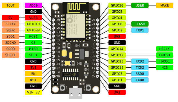
要在ESP8266上運行MicroPython,需要至少1MB的Flash Rom 版本,

(MicroPython Firmware大約佔去512K) ,而Node MCU選用的是ESP12E,

有4MB Flash Rom,十分足夠。


1.首先要下載MicroPython Firmware。

http://micropython.org/download#esp8266

到此連結選擇最新的穩定版本,撰寫本文時最新版本為esp8266-20180511-v1.9.4.bin


2.燒錄工具 (電腦需要有python環境以及pip工具), 建議用python3

pip3 install esptool

3.檔案工具Adafruit MicroPython Tool  (AMPY)

pip3 install adafruit-ampy

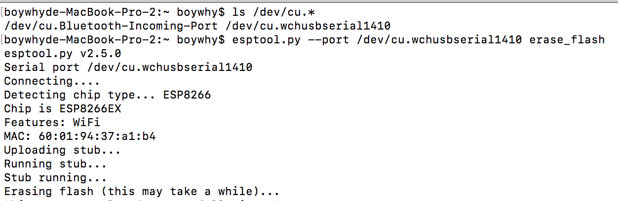
4.將Node MCU連接到電腦 ,確認是否可以看到Node MCU的Serial Port

ls /dev/cu.*


若能夠看到/dev/cu.wchusbserial1410(或1420) 代表能夠捉到Node MCU的Serial Port (驅動成功安裝) , 如果沒有看到

需要確定您使用的Node MCU是使用那一個版本的USB to TTL晶片

若是CH340
安裝以下驅動(安裝完畢後必須重開機,並且在隱私設定中允許)

http://www.wch.cn/download/CH341SER_MAC_ZIP.html


若是CP2102 則安裝以下驅動,並允許隱私權中的設定,然候重開機
https://www.silabs.com/products/development-tools/software/usb-to-uart-bridge-vcp-drivers


5.抺除Node MCU中原廠的Firmware (注意 port可能和我不同)


CH340
esptool.py --port /dev/cu.wchusbserial1410 erase_flash


CP2102


6.寫入MicroPython Firmware

CP2102
esptool.py --port /dev/cu.SLAB_USBtoUART --baud 460800 write_flash --flash_size=detect 0 ~/Downloads/esp8266-20180511-v1.9.4.bin


CH340
esptool.py --port /dev/cu.wchusbserial1410 --baud 115200 write_flash --flash_size=detect 0 ~/Downloads/esp8266-20180511-v1.9.4.bin


7.透過ampy 查詢一下Node MCU中有什麼東要(測試燒錄是否成功)

CH340

ampy --port /dev/cu.wchusbserial1410 ls

出現錯誤 colud not entr raw repl

俺試過加入Delay 2秒也沒用,最後發現跟本是沒有燒好(MBP 2015不會跳錯,但不一定燒錄成功,而MBP 2017則是無法燒錄),在CH340的USB  To TTL晶片記得要在燒錄時把baud 改成 115200.


CP2102
ampy --port /dev/cu.SLAB_USBtoUART  ls


8.到此燒錄MicroPython已完成,接下來寫一個main.py

import time
from machine import Pin

led = Pin(2, Pin.OUT)
led.value(1)

while True:
    led.value(0)
    time.sleep_ms(500)
    led.value(1)
    time.sleep_ms(500)

9.將main.py丟到Node MCU

CP2102
ampy --port /dev/cu.SLAB_USBtoUART  ls
CH340
ampy --port /dev/cu.wchusbserial1410 put  main.py
接下來按下RST鍵,藍色LED就會以0.5秒間隔閃爍。


參考資料:

Malo老師的GitHub

CH340 OSX flash error with speed greater 115200


2018年9月14日 星期五

[Python] [SSL: TLSV1_ALERT_PROTOCOL_VERSION]


在OS X Python 2.7.14使用pip套件安裝出現以下錯誤

There was a problem confirming the ssl certificate: [SSL: TLSV1_ALERT_PROTOCOL_VERSION] tlsv1 alert protocol version (_ssl.c:661) - skipping


在網路上找到一個解法

curl https://bootstrap.pypa.io/get-pip.py | python


之後pip就正常了


參考網頁:

Problem Confirming the SSL Certificate - OSXhttps://github.com/pypa/pip/issues/5236

[Arduino]外部中斷

過去我們在偵測button有沒有按下時,我們會在loop() 中不斷的去檢查button狀態,

但這樣其實效能不佳,我們可以透過中斷,來處理Button按下的問題。

但記住一件事,傳統的button會有彈跳現像,這個我們之後再談。


2018年5月6日 星期日

[EPS8266」Node MCU 使用LCD 1602(5V版本),電壓問題解法

之前遇到一個鳥問題,想要使用Node MCU來手驅動LCD 1602時LCD並不正常,

僅有LCD背光亮起,但無法正常顯示內容,查詢後可能是電壓的問題(NODE MCU

,找到一個不需要另外拉線可以使用5V供電的方法。


手上的nodeMCU 為 v3 LoLin (不同版本的NodeMCU腳位可能略有不同)


找了很多資料都需要額外電路,最後發現,其實左邊第三隻腳VV

就是輸出USB供給的電壓(5V),實際量起來大約4.98V,足夠囉。

「nodemcu  lolin」的圖片搜尋結果


2018年2月26日 星期一

[Android] TextView 的 freezesText

今天在處理當螢幕旋轉問題時,意外看到freezesText這個設定。

先來看一下Android的文件上怎麼說明的

android:freezesText
If set, the text view will include its current complete text inside of its frozen icicle in addition to meta-data such as the current cursor position. By default this is disabled; it can be useful when the contents of a text view is not stored in a persistent place such as a content provider. For EditText it is always enabled, regardless of the value of the attribute.
May be a boolean value, such as "true" or "false".

預設這個設定是關閉的,當你開啟時,它會完整保留TextView上的內容,遊標位置除外。

在EditText中,這個設定總是開啟的。

預設情況下,當我們用在執行過程中,透過程式去設定TextView內容後,當螢幕進行旋轉後,

TextView的內容會消失.


以下是範例程式碼,當按下Add Button後,會把TextView的內容+1
   @Override
    protected void onCreate(Bundle savedInstanceState) {
        super.onCreate(savedInstanceState);
        setContentView(R.layout.activity_main);

        final TextView textView=(TextView)findViewById(R.id.txt);

        Button button=(Button)findViewById(R.id.add);

        button.setOnClickListener(new View.OnClickListener() {
            @Override
            public void onClick(View v) {
                int num=0;
                if (!textView.getText().toString().equals(""))
                {
                    num=Integer.parseInt(textView.getText().toString());
                }


                num++;

                textView.setText(String.valueOf(num));

            }
        });
    }

例如我按了六下Button,目前TextView的內容是6


當我進行螢幕旋轉後,TextView的內容不見囉


如果我將freezesText設為True


<?xml version="1.0" encoding="utf-8"?>
<RelativeLayout xmlns:android="http://schemas.android.com/apk/res/android"
    xmlns:tools="http://schemas.android.com/tools"
    android:layout_width="match_parent"
    android:layout_height="match_parent"
    android:paddingBottom="@dimen/activity_vertical_margin"
    android:paddingLeft="@dimen/activity_horizontal_margin"
    android:paddingRight="@dimen/activity_horizontal_margin"
    android:paddingTop="@dimen/activity_vertical_margin"
    tools:context="com.example.boywhychen.context_menu.MainActivity">


    <TextView
        android:layout_width="wrap_content"
        android:layout_height="wrap_content"
        android:id="@+id/txt"
        android:freezesText="true"
        />

    <Button
        android:layout_width="wrap_content"
        android:layout_height="wrap_content"
        android:id="@+id/add"
        android:text="Add"
        android:layout_below="@+id/txt"
        />
</RelativeLayout>

執行結果如下


它會保留TextView的內容。

參考資料:

https://developer.android.com/reference/android/widget/TextView.html