Electric imp 官網上有提供一個使用UART與Arduino溝通的例子,
小弟實作了一下,約略了一點程式碼。
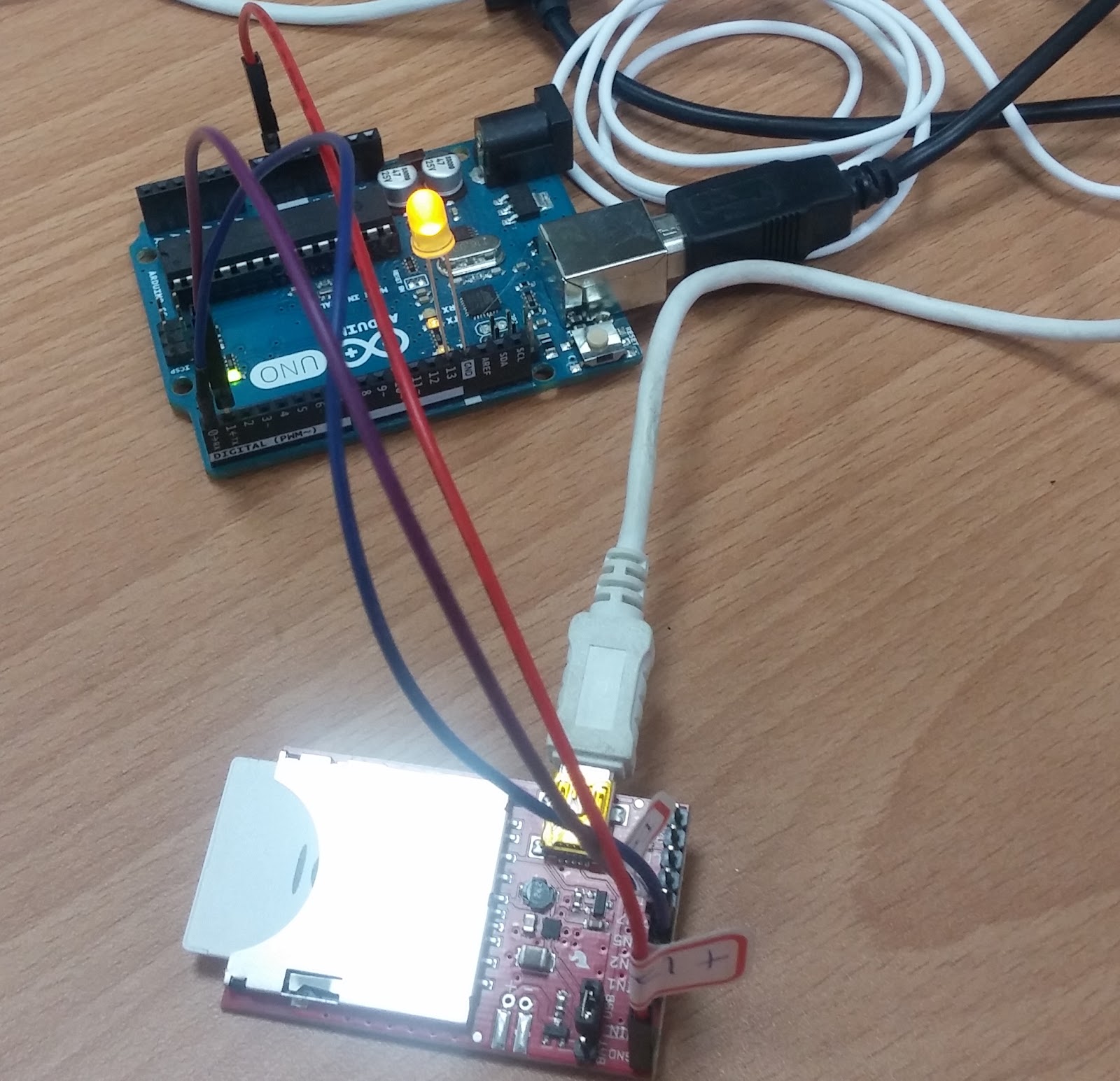
imp001 與擴充版

依照Electric Imp pin mux ,如果使用設定檔為 uart57 的話,Tx是pin5 , Rx是pin7 。
Pin Mux
| Pin | uart 1289 | uart 57 | uart 12 | i2c 89 | i2c 12 | spi 257 | spi 189 | DAC | ADC | PWM | Pulse Count | Wake | PTPG Trigger |
|---|---|---|---|---|---|---|---|---|---|---|---|---|---|
| 1 | CTS | TX | SCL | SCLK | Yes | Yes | Yes | Yes | Yes | ||||
| 2 | RTS | RX | SDA | MISO | Yes | Yes | |||||||
| 5 | TX | SCLK | Yes | Yes | Yes | For Pin 7 | |||||||
| 7 | RX | MOSI | Yes | Yes | |||||||||
| 8 | TX | SCL | MOSI | Yes | Yes | For Pin 5 or 9 | |||||||
| 9 | RX | SDA | MISO | Yes | Yes | For Pin 2 |
The imp supports speeds of between 460 and 1,875,000 Baud on uart12 and uart57, rising to 920-3,750,000 Baud with uart1289. That’s a wide range of speeds; select one which the device you’re connecting will support. The most commonly used speeds are 9600 Baud and 115,200 Baud, which all three imp UARTs support.
arduino imp001
Tx(D1) pin7
Rx(D0) pin5
GND GND


imp001
server.log("Device Started");

function arduinoData() {
    // Read the UART for data sent by Arduino to indicate the state of its LED.

    local b = arduino.read();
    while (b != -1) {
        // As long as UART read value is not -1, we're getting data
        local state = "Unknown";
        if (b == 0x10) state = "Off";
        if (b == 0x11) state = "On"
        server.log("LED: " + state);
        b = arduino.read();
    }
}

function blink(state) {
    // Write state (1 or 0) to the Arduino
    server.log("Setting LED to: " + state);
    arduino.write(state);
    imp.wakeup(1.0, function(){ blink(1 - state); });
}

// Alias UART to which Arduino is connected and configure UART
arduino <- hardware.uart57;
arduino.configure(9600, 8, PARITY_NONE, 1, NO_CTSRTS, arduinoData);

// Start blinking
blink(1);
blink(state)這個函式,每秒會傳送一次與上次相反的state值給arduino。
arduinoData()這個函式只付責讀取arduino送過來的值,並log印出狀態文字。
arduino
// Arduino device code

int led = 13;               // LED pin number

void setup() {
    Serial.begin(9600);     // Configure serial
    pinMode(led, OUTPUT);   // Configure LED pin
    digitalWrite(led, 0);   // Turn LED off
}

void loop() {
    int b = 0;

    // If there's data available
    if (Serial.available() > 0) {
        // Read a byte
        b = Serial.read();

        if (b == 0x00) {
            digitalWrite(led, LOW);
            Serial.write(0x10);
        } else if (b == 0x01) {
            digitalWrite(led, HIGH);
            Serial.write(0x11);
        }
    }
}
view raw
當arduino收到由Serial送過來的值時,若是0則將LED熄滅,並回送一個1的值給imp001,
若是收到1則日是點亮LED,並回傳0的值給imp001。
如果你想要看到arduino實際收到的內容,你可以改用 SoftwareSerial 方式,
把原本的Serial留給電腦接USB看,程式碼如下
#include <SoftwareSerial.h>

SoftwareSerial mySerial(10, 11); // RX, TX
int led = 13;
void setup() {
  // Open serial communications and wait for port to open:
  Serial.begin(9600);
   pinMode(led, OUTPUT);   // Configure LED pin
    digitalWrite(led, 0);   // Turn LED off


  // set the data rate for the SoftwareSerial port
  mySerial.begin(9600);

}

void loop() { // run over and over
  int b=0;
  if (mySerial.available()>0) {
    //Serial.write(mySerial.read());
      b = mySerial.read();
        if (b == 0x00) {
            digitalWrite(led, LOW);
            mySerial.write(0x10);
        } else if (b == 0x01) {
            digitalWrite(led, HIGH);
            mySerial.write(0x11);
        }
        Serial.println(b);
  }
  if (Serial.available()) {
    mySerial.write(Serial.read());
  }
}
但你要把接角換一下,
imp001 arduino
pin7 D11
pin5 D10
此時就可以看序列埠中觀看收到的資料了

參考資料:
https://electricimp.com/docs/resources/uart/
https://electricimp.com/docs/api/hardware/uart/configure/
沒有留言:
張貼留言