僅有LCD背光亮起,但無法正常顯示內容,查詢後可能是電壓的問題(NODE MCU
,找到一個不需要另外拉線可以使用5V供電的方法。
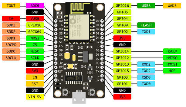
手上的nodeMCU 為 v3 LoLin (不同版本的NodeMCU腳位可能略有不同)

找了很多資料都需要額外電路,最後發現,其實左邊第三隻腳VV,
就是輸出USB供給的電壓(5V),實際量起來大約4.98V,足夠囉。


#include "DHT.h"
#include <ESP8266WiFi.h>
#include <PubSubClient.h>

#define DHTPIN 2     // what digital pin we're connected to

#define DHTTYPE DHT22   // DHT 22  (AM2302), AM2321
// NOTE: If using a board with 3.3V logic like an Arduino Due connect pin 1
// to 3.3V instead of 5V!
// Connect pin 2 of the sensor to whatever your DHTPIN is
// Connect pin 4 (on the right) of the sensor to GROUND
// Initialize DHT sensor.
// Note that older versions of this library took an optional third parameter to
// tweak the timings for faster processors.  This parameter is no longer needed
// as the current DHT reading algorithm adjusts itself to work on faster procs.
DHT dht(DHTPIN, DHTTYPE);

// Update these with values suitable for your network.
const char* ssid = "your ssid";
const char* password = "your pw";
const char* mqtt_server = "MQTT Server IP";
const char* topic="your Topic";
// WiFi Client
WiFiClient espClient;
// PubSub Client
PubSubClient client(espClient);
long lastMsg = 0;
char msg[50];
int value = 0;

void setup() {
  Serial.begin(9600);
  Serial.println("DHTxx test!");
  setup_wifi();
  client.setServer(mqtt_server, 1883);
  client.setCallback(callback);

  dht.begin();
}

void loop() {
  // Wait a few seconds between measurements.
  delay(2000);
 //Check Wi-Fi is Connected
  if (WiFi.status() != WL_CONNECTED)
  {
    setup_wifi();
  }
  //Check MQTT Connection
if (!client.connected()) {
reconnect();
}
client.loop();
// Reading temperature or humidity takes about 250 milliseconds!
// Sensor readings may also be up to 2 seconds 'old' (its a very slow sensor)
float h = dht.readHumidity();
// Read temperature as Celsius (the default)
float t = dht.readTemperature();
// Read temperature as Fahrenheit (isFahrenheit = true)
float f = dht.readTemperature(true);
// Check if any reads failed and exit early (to try again).
if (isnan(h) || isnan(t) || isnan(f)) {
Serial.println("Failed to read from DHT sensor!");
return;
}
// Compute heat index in Fahrenheit (the default)
float hif = dht.computeHeatIndex(f, h);
// Compute heat index in Celsius (isFahreheit = false)
float hic = dht.computeHeatIndex(t, h, false);
Serial.print("Humidity: ");
Serial.print(h);
Serial.print(" %\t");
Serial.print("Temperature: ");
Serial.print(t);
Serial.print(" *C ");
Serial.print(f);
Serial.print(" *F\t");
Serial.print("Heat index: ");
Serial.print(hic);
Serial.print(" *C ");
Serial.print(hif);
Serial.println(" *F");
long now = millis();
// read DHT22 sensor every 6 seconds
if (now - lastMsg > 6000) {
lastMsg = now;
String msg=String(h)+","+String(t);
Serial.println(msg);
char message[msg.length()];
msg.toCharArray(message,msg.length());
//publish sensor data to MQTT broker
client.publish(topic, message);
}
}
void setup_wifi() {
delay(100);
// We start by connecting to a WiFi network
Serial.print("Connecting to ");
Serial.println(ssid);
WiFi.begin(ssid, password);
while (WiFi.status() != WL_CONNECTED)
{
delay(500);
Serial.print(".");
}
randomSeed(micros());
Serial.println("");
Serial.println("WiFi connected");
Serial.println("IP address: ");
Serial.println(WiFi.localIP());
}
// recieve Topic message handler , I don't implements it
void callback(char* topic, byte* payload, unsigned int length)
{
}
void reconnect() {
// Loop until we're reconnected
while (!client.connected())
{
Serial.print("Attempting MQTT connection...");
// Create a random client ID
String clientId = "ESP8266Client-";
clientId += String(random(0xffff), HEX);
// Attempt to connect
//if you MQTT broker has clientID,username and password
//please change following line to if (client.connect(clientId,userName,passWord))
if (client.connect(clientId.c_str()))
{
Serial.println("connected");
//once connected to MQTT broker, subscribe command if any
client.subscribe(topic);
} else {
Serial.print("failed, rc=");
Serial.print(client.state());
Serial.println(" try again in 5 seconds");
// Wait 6 seconds before retrying
delay(6000);
}
}
} //end reconnect()


sudo esptool.py -p /dev/cu.SLAB_USBtoUART -b 115200 write_flash 0x00000 boot_v1.6.bin 0x01000 ESP8266_NONOS_SDK/bin/at/512+512/user1.1024.new.2.bin 0xfc000 ESP8266_NONOS_SDK/bin/esp_init_data_default.bin 0x7e000 ESP8266_NONOS_SDK/bin/blank.bin
esptool.py v1.0.1
Connecting...
Erasing flash...
Took 0.13s to erase flash block
Wrote 4096 bytes at 0x00000000 in 0.4 seconds (81.1 kbit/s)...
Erasing flash...
Took 2.60s to erase flash block
Wrote 419840 bytes at 0x00001000 in 41.0 seconds (81.9 kbit/s)...
Erasing flash...
Took 0.09s to erase flash block
Wrote 1024 bytes at 0x000fc000 in 0.1 seconds (85.2 kbit/s)...
Erasing flash...
Took 0.15s to erase flash block
Wrote 4096 bytes at 0x0007e000 in 0.4 seconds (85.4 kbit/s)...

Leaving...


#include <LiquidCrystal_I2C.h>
#include <Wire.h>
#include <ESP8266WiFi.h>
#include <OneWire.h>
#define SensorPin A0           //pH meter Analog output to Arduino Analog Input 0
#define Offset 0.42           //deviation compensate
#define samplingInterval 20
#define printInterval 800
#define ArrayLenth  40    //times of collection
int pHArray[ArrayLenth];   //Store the average value of the sensor feedback
int pHArrayIndex=0;
OneWire  ds(14);  // on pin 14 (a 4.7K resistor is necessary)
// replace with your channel’s thingspeak API key,
String apiKey = "your ThingSpeak API Key";
const char* ssid = "your ssid";
const char* password = "your password";

const char* server = "api.thingspeak.com";
LiquidCrystal_I2C lcd(0x27,16,2); // Check I2C address of LCD, normally 0x27 or 0x3F
static const byte degrees_glyph[] = { 0x00, 0x07, 0x05, 0x07, 0x00 };
WiFiClient client;


void setup()  {
lcd.begin(4,5);      // In ESP8266-01, SDA=0, SCL=2
lcd.backlight();
// Register the custom symbol...
Serial.begin(115200);
delay(10);
Serial.println();
Serial.println();
Serial.print("Connecting to ");
Serial.println(ssid);

WiFi.begin(ssid, password);

while (WiFi.status() != WL_CONNECTED) {
delay(500);
Serial.print(".");
}
Serial.println("");
Serial.println("WiFi connected");
}

void loop()  {
byte i;
byte present = 0;
byte type_s;
byte data[12];
byte addr[8];
float celsius, fahrenheit;
int h=20;

if ( !ds.search(addr)) {
    Serial.println("No more addresses.");
    Serial.println();
    ds.reset_search();
    delay(250);
    return;
  }

  Serial.print("ROM =");
  for( i = 0; i < 8; i++) {
    Serial.write(' ');
    Serial.print(addr[i], HEX);
  }

  if (OneWire::crc8(addr, 7) != addr[7]) {
      Serial.println("CRC is not valid!");
      return;
  }
  Serial.println();

  // the first ROM byte indicates which chip
  switch (addr[0]) {
    case 0x10:
      Serial.println("  Chip = DS18S20");  // or old DS1820
      type_s = 1;
      break;
    case 0x28:
      Serial.println("  Chip = DS18B20");
      type_s = 0;
      break;
    case 0x22:
      Serial.println("  Chip = DS1822");
      type_s = 0;
      break;
    default:
      Serial.println("Device is not a DS18x20 family device.");
      return;
  }

  ds.reset();
  ds.select(addr);
  ds.write(0x44, 1);        // start conversion, with parasite power on at the end

  delay(1000);     // maybe 750ms is enough, maybe not
  // we might do a ds.depower() here, but the reset will take care of it.

  present = ds.reset();
  ds.select(addr);
  ds.write(0xBE);         // Read Scratchpad

  Serial.print("  Data = ");
  Serial.print(present, HEX);
  Serial.print(" ");
  for ( i = 0; i < 9; i++) {           // we need 9 bytes
    data[i] = ds.read();
    Serial.print(data[i], HEX);
    Serial.print(" ");
  }
  Serial.print(" CRC=");
  Serial.print(OneWire::crc8(data, 8), HEX);
  Serial.println();

  // Convert the data to actual temperature
  // because the result is a 16 bit signed integer, it should
  // be stored to an "int16_t" type, which is always 16 bits
  // even when compiled on a 32 bit processor.
  int16_t raw = (data[1] << 8) | data[0];
  if (type_s) {
    raw = raw << 3; // 9 bit resolution default
    if (data[7] == 0x10) {
      // "count remain" gives full 12 bit resolution
      raw = (raw & 0xFFF0) + 12 - data[6];
    }
  } else {
    byte cfg = (data[4] & 0x60);
    // at lower res, the low bits are undefined, so let's zero them
    if (cfg == 0x00) raw = raw & ~7;  // 9 bit resolution, 93.75 ms
    else if (cfg == 0x20) raw = raw & ~3; // 10 bit res, 187.5 ms
    else if (cfg == 0x40) raw = raw & ~1; // 11 bit res, 375 ms
    //// default is 12 bit resolution, 750 ms conversion time
  }
  celsius = (float)raw / 16.0;
  fahrenheit = celsius * 1.8 + 32.0;
  Serial.print("  Temperature = ");
  Serial.print(celsius);
  Serial.print(" Celsius, ");
  Serial.print(fahrenheit);
  Serial.println(" Fahrenheit");
  static unsigned long samplingTime = millis();
  static unsigned long printTime = millis();
  static float pHValue,voltage;
  if(millis()-samplingTime > samplingInterval)
  {
      pHArray[pHArrayIndex++]=analogRead(SensorPin);
      if(pHArrayIndex==ArrayLenth)pHArrayIndex=0;
      voltage = avergearray(pHArray, ArrayLenth)*5.0/1024;
      pHValue = 3.5*voltage+Offset;
      samplingTime=millis();
  }
  if(millis() - printTime > printInterval)   //Every 800 milliseconds, print a numerical, convert the state of the LED indicator
  {
    Serial.print("Voltage:");
    Serial.print(voltage,2);
    Serial.print("    pH value: ");
    Serial.println(pHValue,2);
    printTime=millis();
  }


if (client.connect(server,80)) { // "184.106.153.149" or api.thingspeak.com
String postStr = apiKey;
postStr +="&field1=";
postStr += String(celsius);
postStr +="&field2=";
postStr += String(pHValue);
postStr += "\r\n\r\n";

client.print("POST /update HTTP/1.1\n");
client.print("Host: api.thingspeak.com\n");
client.print("Connection: close\n");
client.print("X-THINGSPEAKAPIKEY: "+apiKey+"\n");
client.print("Content-Type: application/x-www-form-urlencoded\n");
client.print("Content-Length: ");
client.print(postStr.length());
client.print("\n\n");
client.print(postStr);
lcd.setCursor(0, 0);
lcd.print("Temperature:");
lcd.print(celsius,1);
lcd.setCursor(0, 1);
lcd.print("PH Value:");
lcd.print(pHValue,1);
Serial.print("Temperature: ");
Serial.print(celsius);
Serial.print("PH: ");
Serial.print(pHValue);
Serial.println("send to Thingspeak");
}
client.stop();

Serial.println("Waiting…");
// thingspeak needs minimum 15 sec delay between updates
delay(20000);
}
double avergearray(int* arr, int number){
  int i;
  int max,min;
  double avg;
  long amount=0;
  if(number<=0){
    Serial.println("Error number for the array to avraging!/n");
    return 0;
  }
  if(number<5){   //less than 5, calculated directly statistics
    for(i=0;i<number;i++){
      amount+=arr[i];
    }
    avg = amount/number;
    return avg;
  }else{
    if(arr[0]<arr[1]){
      min = arr[0];max=arr[1];
    }
    else{
      min=arr[1];max=arr[0];
    }
    for(i=2;i<number;i++){
      if(arr[i]<min){
        amount+=min;        //arr<min
        min=arr[i];
      }else {
        if(arr[i]>max){
          amount+=max;    //arr>max
          max=arr[i];
        }else{
          amount+=arr[i]; //min<=arr<=max
        }
      }//if
    }//for
    avg = (double)amount/(number-2);
  }//if
  return avg;
}


/*

 Udp NTP Client

 Get the time from a Network Time Protocol (NTP) time server
 Demonstrates use of UDP sendPacket and ReceivePacket
 For more on NTP time servers and the messages needed to communicate with them,
 see http://en.wikipedia.org/wiki/Network_Time_Protocol

 created 4 Sep 2010
 by Michael Margolis
 modified 9 Apr 2012
 by Tom Igoe
 updated for the ESP8266 12 Apr 2015
 by Ivan Grokhotkov

 This code is in the public domain.

 */
#include <Wire.h>
#include <LiquidCrystal_I2C.h>
#include <ESP8266WiFi.h>
#include <WiFiUdp.h>

char ssid[] = "GFI-5F-ID";  //  your network SSID (name)
char pass[] = "gfi8158456";       // your network password
char data[8];
char buffer[2];

unsigned int localPort = 2390;      // local port to listen for UDP packets

/* Don't hardwire the IP address or we won't get the benefits of the pool.
 *  Lookup the IP address for the host name instead */
//IPAddress timeServer(129, 6, 15, 28); // time.nist.gov NTP server
IPAddress timeServerIP; // time.nist.gov NTP server address
const char* ntpServerName = "time.nist.gov";

const int NTP_PACKET_SIZE = 48; // NTP time stamp is in the first 48 bytes of the message

byte packetBuffer[ NTP_PACKET_SIZE]; //buffer to hold incoming and outgoing packets

// A UDP instance to let us send and receive packets over UDP
WiFiUDP udp;
LiquidCrystal_I2C lcd(0x27, 16, 2);

void setup()
{
  Serial.begin(115200);
  Serial.println();
  Serial.println();

  // initialize the LCD
  lcd.begin(0,2);  // sda=0, scl=2

  // Turn on the blacklight and print a message.
  lcd.backlight();
  lcd.print("NTP Client");

  // We start by connecting to a WiFi network
  Serial.print("Connecting to ");
  Serial.println(ssid);
  WiFi.begin(ssid, pass);

  while (WiFi.status() != WL_CONNECTED) {
    delay(500);
    Serial.print(".");
  }
  Serial.println("");

  Serial.println("WiFi connected");
  Serial.println("IP address: ");
  Serial.println(WiFi.localIP());

  Serial.println("Starting UDP");
  udp.begin(localPort);
  Serial.print("Local port: ");
  Serial.println(udp.localPort());
}

void loop()
{
  //get a random server from the pool
  WiFi.hostByName(ntpServerName, timeServerIP);

  sendNTPpacket(timeServerIP); // send an NTP packet to a time server
  // wait to see if a reply is available
  delay(1000);

  int cb = udp.parsePacket();
  if (!cb) {
    Serial.println("no packet yet");
  }
  else {
    Serial.print("packet received, length=");
    Serial.println(cb);
    // We've received a packet, read the data from it
    udp.read(packetBuffer, NTP_PACKET_SIZE); // read the packet into the buffer

    //the timestamp starts at byte 40 of the received packet and is four bytes,
    // or two words, long. First, esxtract the two words:

    unsigned long highWord = word(packetBuffer[40], packetBuffer[41]);
    unsigned long lowWord = word(packetBuffer[42], packetBuffer[43]);
    // combine the four bytes (two words) into a long integer
    // this is NTP time (seconds since Jan 1 1900):
    unsigned long secsSince1900 = highWord << 16 | lowWord;
    Serial.print("Seconds since Jan 1 1900 = " );
    Serial.println(secsSince1900);

    // now convert NTP time into everyday time:
    Serial.print("Unix time = ");
    // Unix time starts on Jan 1 1970. In seconds, that's 2208988800:
    const unsigned long seventyYears = 2208988800UL;
    // subtract seventy years:
    unsigned long epoch = secsSince1900 - seventyYears;
    // print Unix time:
    Serial.println(epoch);

    //clear lcd
    lcd.clear();

    // print the hour, minute and second:
    Serial.print("The UTC time is ");       // UTC is the time at Greenwich Meridian (GMT)
    lcd.print("The UTC time is ");
    lcd.setCursor(0,1);
    Serial.print((epoch  % 86400L) / 3600); // print the hour (86400 equals secs per day)

     if ( ((epoch % 3600) / 60) < 10 ) {
       lcd.print('0');
     }
     lcd.print(((epoch  % 86400L) / 3600)+8);
    Serial.print(':');
    lcd.print(':');
    if ( ((epoch % 3600) / 60) < 10 ) {
      // In the first 10 minutes of each hour, we'll want a leading '0'
      Serial.print('0');
      lcd.print('0');
    }
    Serial.print((epoch  % 3600) / 60); // print the minute (3600 equals secs per minute)
    Serial.print(':');
    lcd.print((epoch  % 3600) / 60); // print the minute (3600 equals secs per minute)
    lcd.print(':');
    if ( (epoch % 60) < 10 ) {
      // In the first 10 seconds of each minute, we'll want a leading '0'
      Serial.print('0');
      lcd.print('0');
    }
    Serial.println(epoch % 60); // print the second
    lcd.print(epoch % 60);
  }
  // wait ten seconds before asking for the time again
  delay(10000);
}

// send an NTP request to the time server at the given address
unsigned long sendNTPpacket(IPAddress& address)
{
  Serial.println("sending NTP packet...");
  // set all bytes in the buffer to 0
  memset(packetBuffer, 0, NTP_PACKET_SIZE);
  // Initialize values needed to form NTP request
  // (see URL above for details on the packets)
  packetBuffer[0] = 0b11100011;   // LI, Version, Mode
  packetBuffer[1] = 0;     // Stratum, or type of clock
  packetBuffer[2] = 6;     // Polling Interval
  packetBuffer[3] = 0xEC;  // Peer Clock Precision
  // 8 bytes of zero for Root Delay & Root Dispersion
  packetBuffer[12]  = 49;
  packetBuffer[13]  = 0x4E;
  packetBuffer[14]  = 49;
  packetBuffer[15]  = 52;

  // all NTP fields have been given values, now
  // you can send a packet requesting a timestamp:
  udp.beginPacket(address, 123); //NTP requests are to port 123
  udp.write(packetBuffer, NTP_PACKET_SIZE);
  udp.endPacket();
}


